Dies ist eine alte Version des Dokuments!
Inhaltsverzeichnis
DIYPowerPCB
Introduction
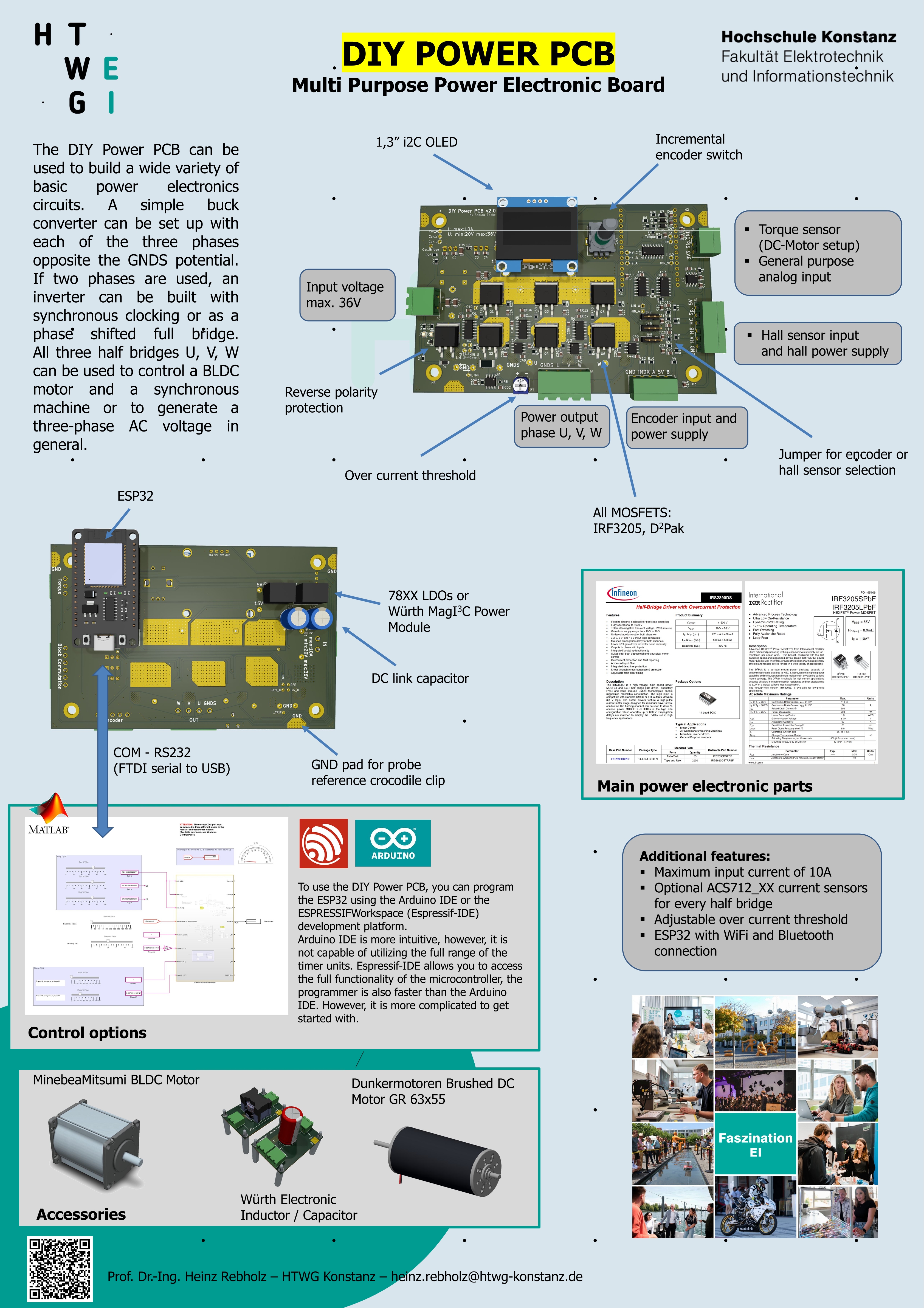
Theoretical derivations in a lecture are part of everyday university life. But you can only really get to grips with topics if you apply what you have learned! For this reason, we have developed the DIY Power PCB. This enables us to provide all interested students with their own hardware platform to carry out a wide variety of experiments on the subject of power electronics.
The idea was not to build the most powerful or the smallest hardware, but a hardware whose components can largely be assembled automatically and which is above all inexpensive and robust. So no worries if a short circuit is generated or smoke rises 
The DIY Power PCB is used in various experiments in the lectures on power electronics and electrical drives and costs less than 20€ for our students when fully assembled.
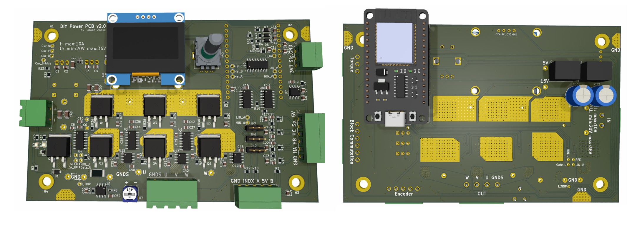
Parameters:
- 3x half bridges
- Adjustable overcurrent shutdown
- ESP32 Wroom microcontroller
- 1.36 OLED display
- Max. 36V @10A input
- Hall sensor or encoder inputs
- General purpose analog input
- Reverse polarity protection
The brain of the board is represented by an ESP32 microcontroller. This controller is very powerful and widely available at affordable prices. You can directly program it using the Arduino IDE or ESP-IDF. For lab lessons, you will use a serial communication interface between MATLAB Simulink and the controller to command the board.
Schematic: schematic_diy_power_pcb.pdf
To use the DIY Power PCB, you can program the ESP32 using the Arduino IDE or the ESPRESSIFWorkspace (Espressif-IDE) development platform. Arduino IDE is more intuitive; however, it is not capable of utilizing the full range of the timer units. Espressif-IDE allows you to access the full functionality of the microcontroller, and the programmer is also faster than the Arduino IDE. However, it is more complicated to get started with.
Board Flyer
Isolation
In many of our experiments, we control the hardware via the serial interface. To protect the connected PC, you should use galvanic isolation between the PC and the microcontroller board when the supply voltage is active. This prevents overvoltages from destroying the USB port even in the event of major errors in the setup (short circuit or load dump) on the control PC.
The isolators are available in the laboratory.
z.B.
